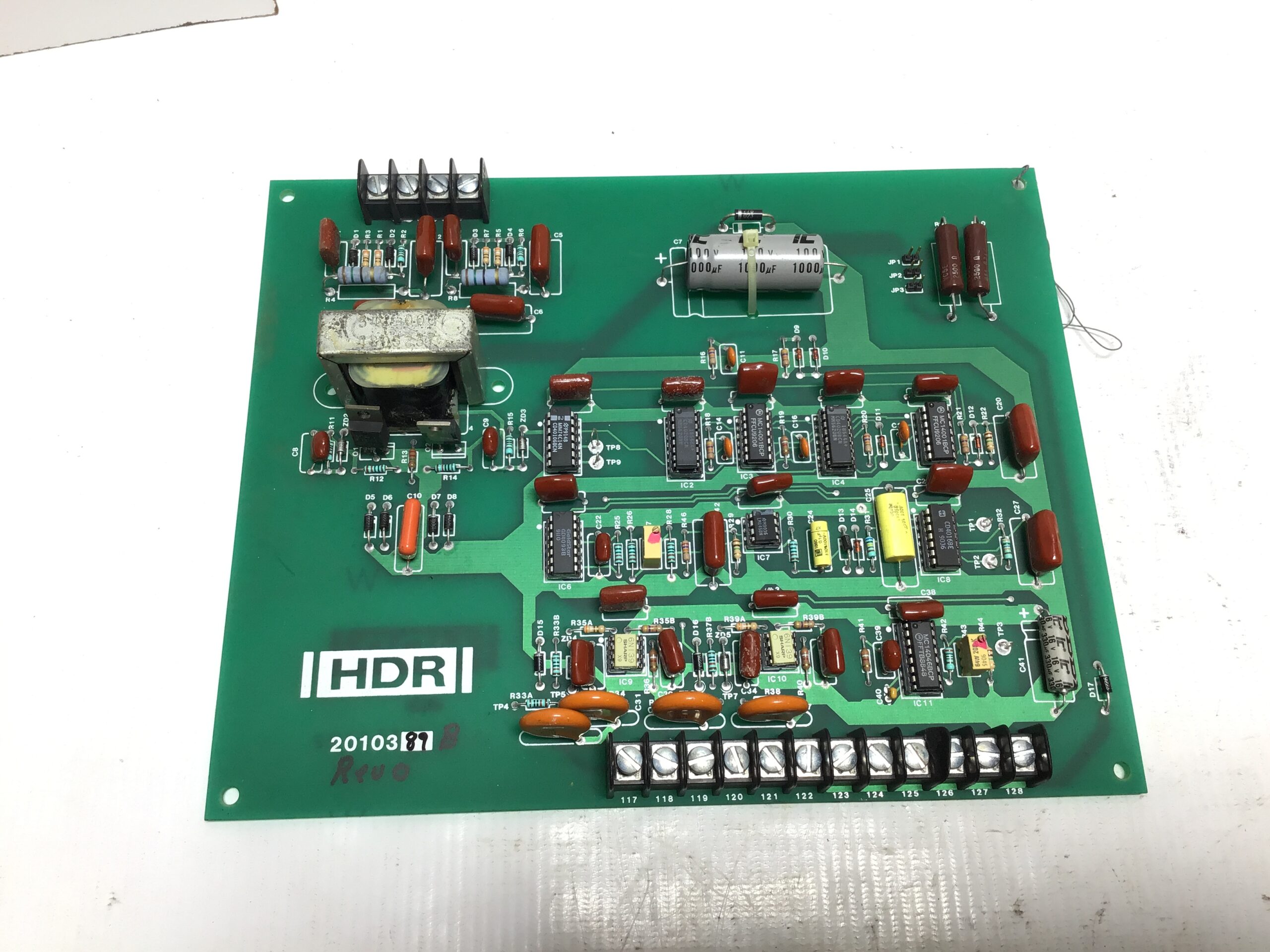
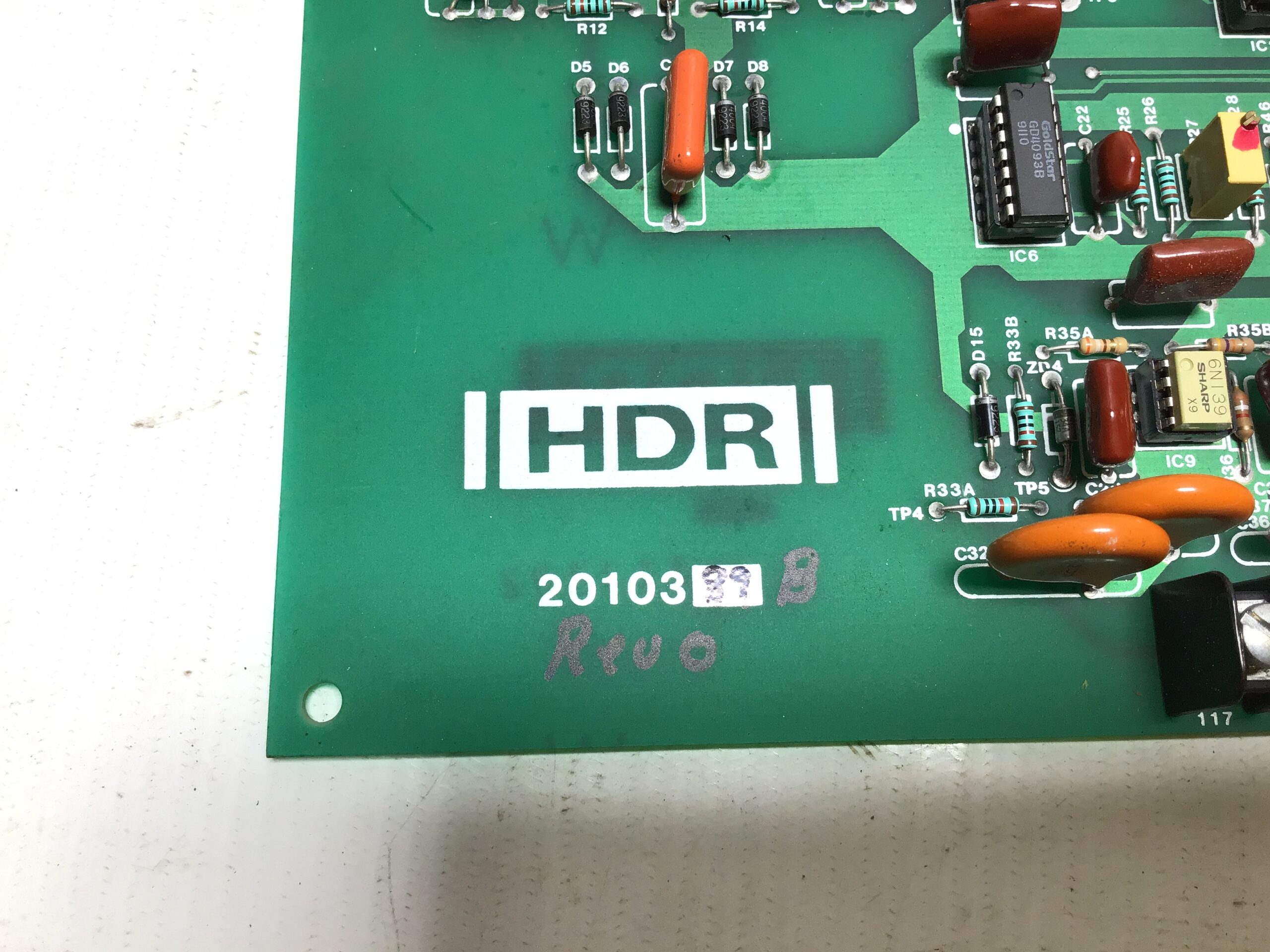
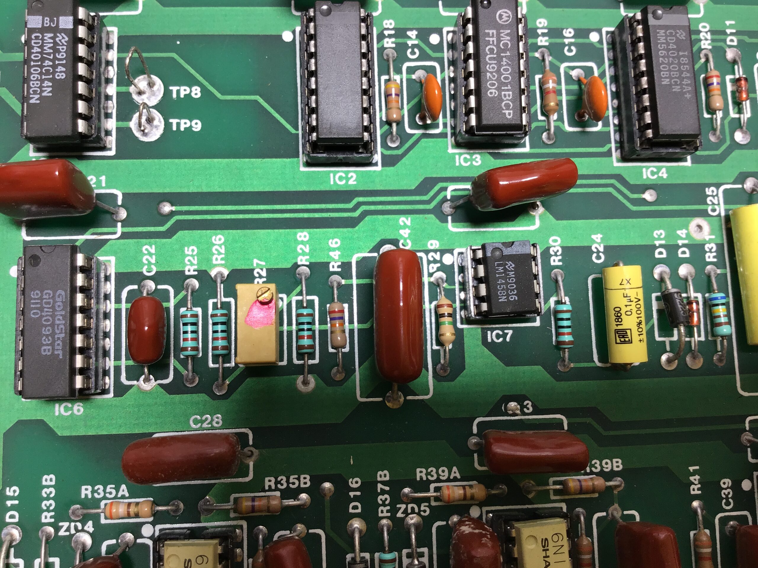
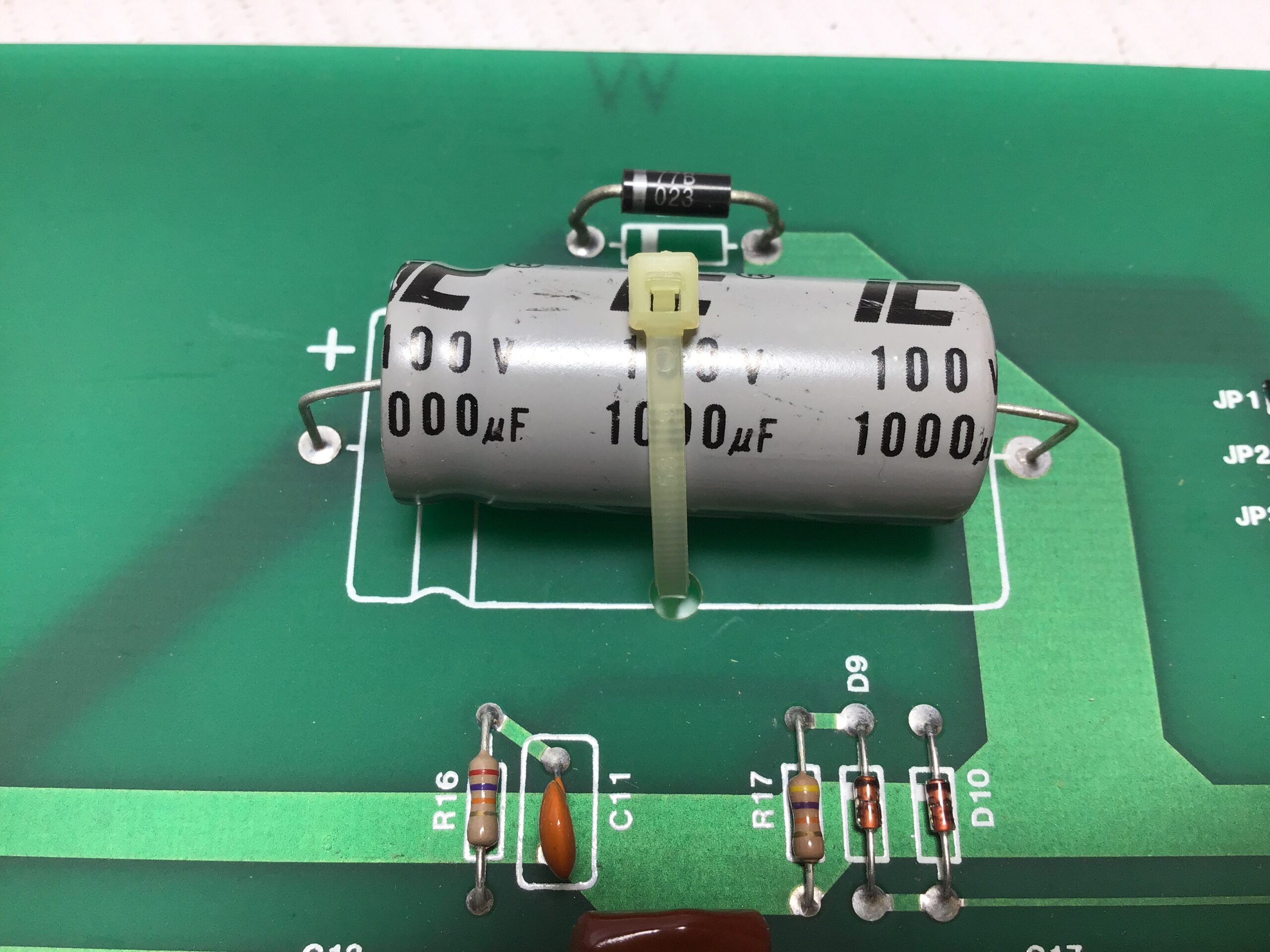
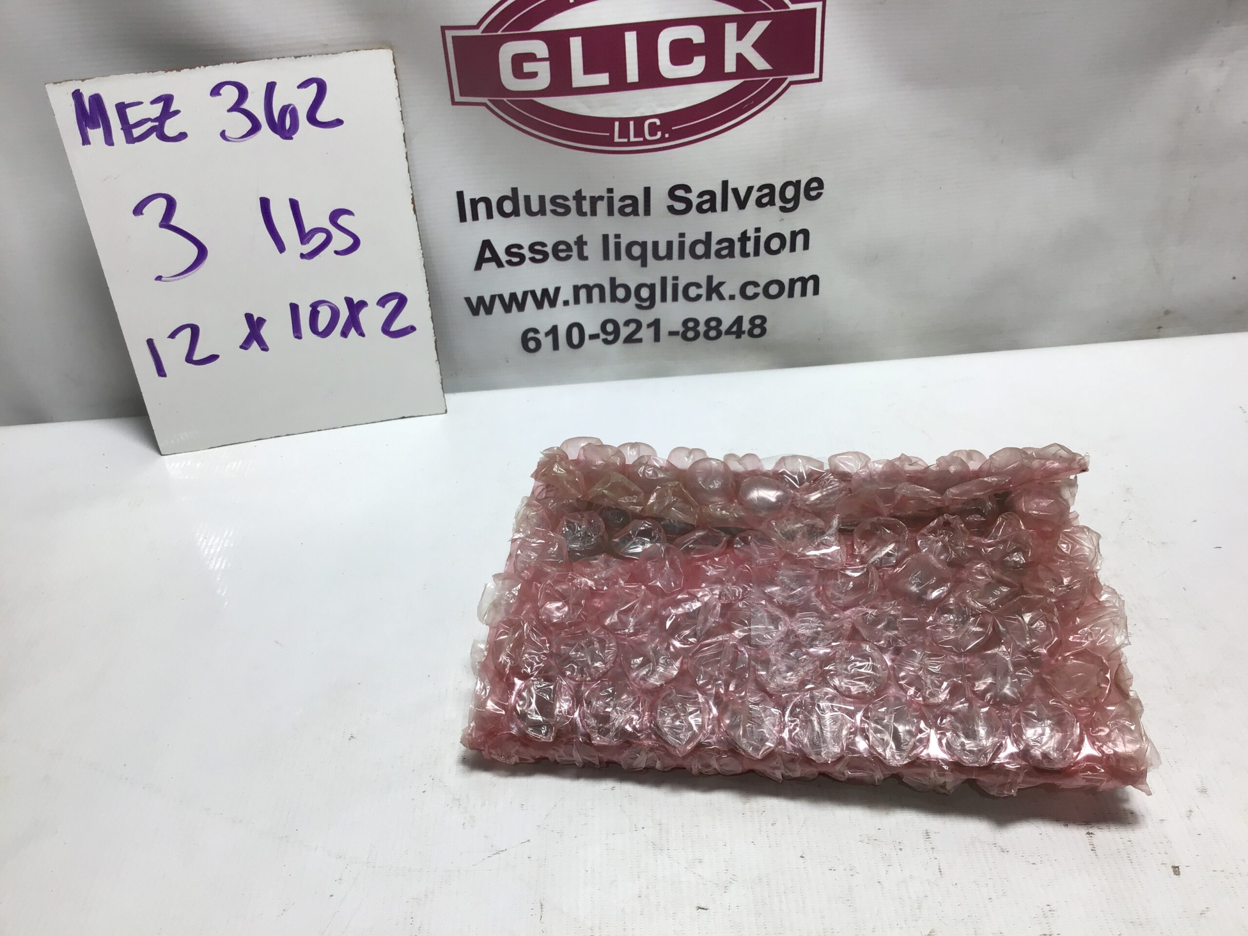
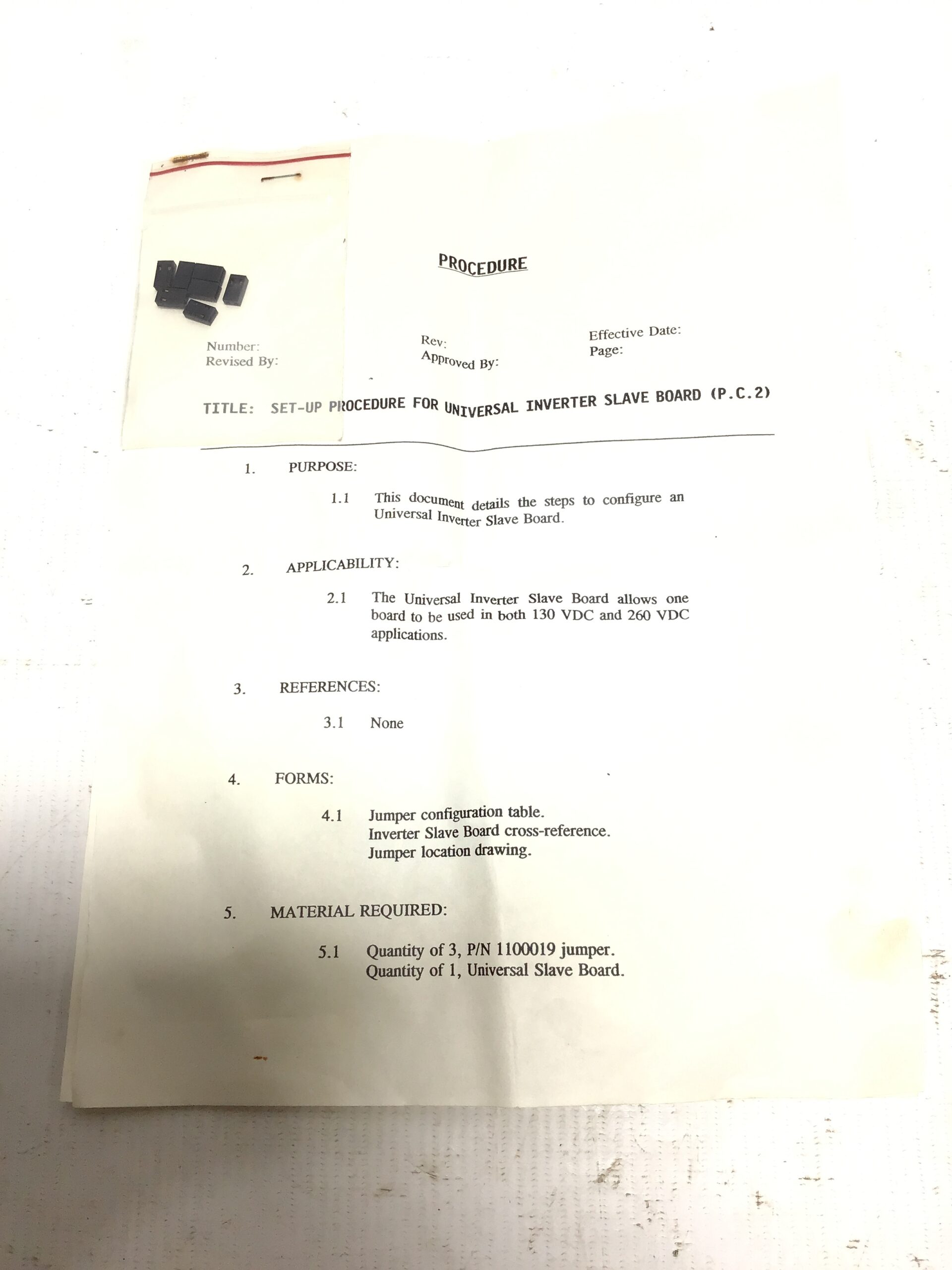
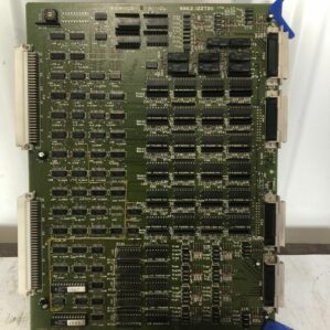
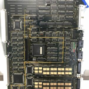
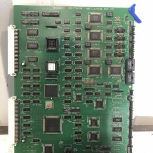
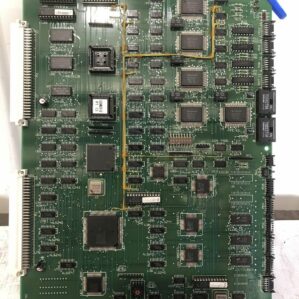
The NEW, HDR 80-H2010389-90 Oscillator PCB (Circuit Board) seems to be a specific part number for a type of oscillator circuit board produced by HDR (High Density Resistor) or another manufacturer. Unfortunately, I do not have direct access to all part numbers or detailed product data beyond what is publicly available, but I can offer an outline of what a PCB Oscillator circuit board like this might typically include, based on standard industry practices for similar components.
NEW, HDR 80-H2010389-90 Oscillator PCB: Product Outline
1. General Overview:
- The HDR 80-H2010389-90 Oscillator PCB is likely a printed circuit board (PCB) designed to house an oscillator circuit, used in a variety of applications where stable and precise frequencies are required.
- An oscillator is an electronic circuit that generates a periodic waveform (sine, square, or triangular wave) used for generating clocks, radio frequencies, timing signals, and more.
- This specific part number could be related to a high-frequency oscillator, a signal generator, or a timing circuit, typically used in telecommunications, signal processing, or other high-precision applications.
2. Key Features & Functions:
- Frequency Generation: The primary function of the PCB would be to generate specific frequencies required for the application. This could involve generating sine, square, or pulse waveforms at different frequencies, often stable and accurate.
- Precision Control: The oscillator is likely designed for high precision, ensuring minimal drift and accurate frequency output over time and temperature variations.
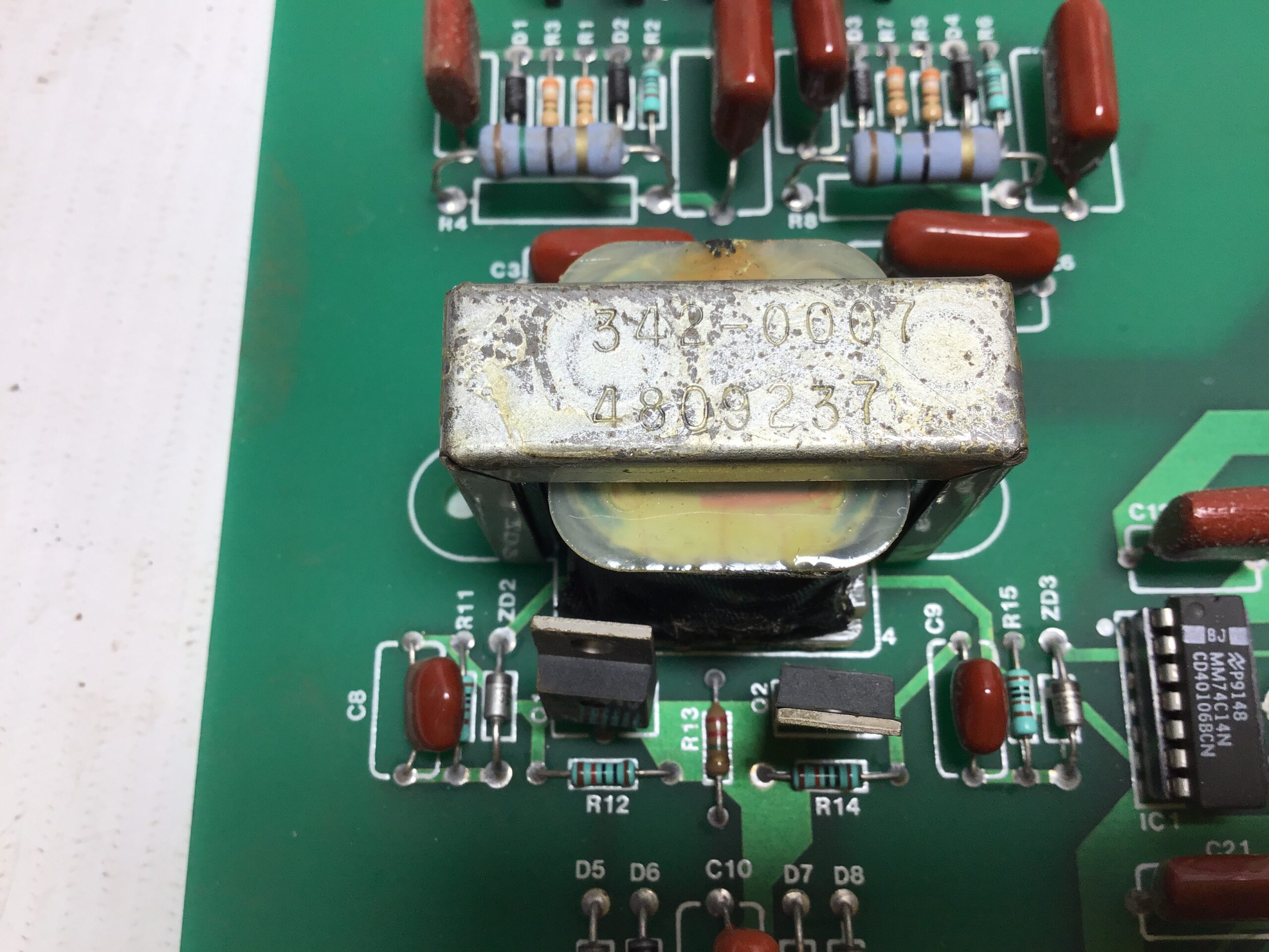
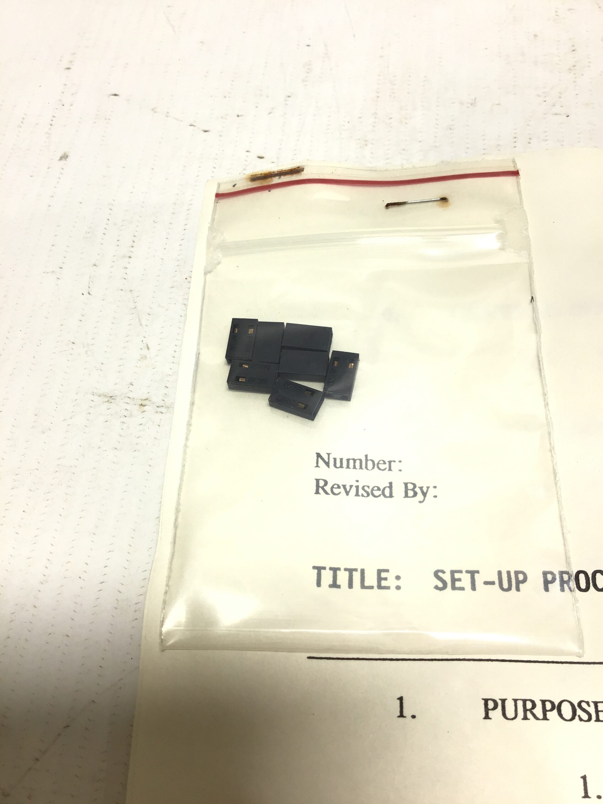
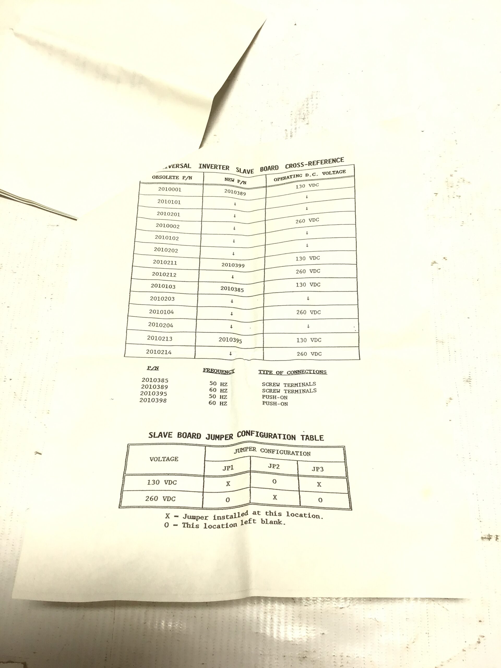
- Integrated Components: Likely integrates various components such as resistors, capacitors, inductors, crystals (for crystal oscillators), and transistors or ICs to form a functional oscillator circuit.
- Signal Output: The PCB would provide various outputs (e.g., sine, square, or triangular waves) at specific frequencies, depending on the application. These could be low-impedance or high-impedance, with output voltage levels that meet the needs of the end application.
- Adjustability: Some oscillators feature adjustable output frequency or duty cycle, which could be incorporated on this board.
- Power Supply: The oscillator circuit may have specific power requirements (e.g., +5V, +12V, or +15V) to drive the internal circuit and produce the desired output.
3. Possible Applications:
- Communication Systems:
- Oscillators are often used in radio frequency (RF) communication systems, both analog and digital, to generate carriers for modulated signals.
- This PCB might be used in RF signal generators or frequency synthesizers.
- Clock Generation:
- In digital systems, oscillators generate clock signals required by microcontrollers, microprocessors, or logic circuits to synchronize data flow.
- Test Equipment:
- Oscillator PCBs like this one could be used in signal generators for test equipment, allowing engineers to inject controlled signals into circuits for analysis or testing.
- Timing and Control:
- Oscillators are essential for generating accurate time signals for applications such as timing chips, frequency counters, and synchronizing communication protocols.
- Signal Processing:
- Oscillators are often integrated into systems that require specific frequency outputs for analog signal processing, such as filters, mixers, or amplifiers.
4. Specifications (Hypothetical):
- Output Frequency Range: Depending on the design, the oscillator could cover a broad range of frequencies, from low frequencies (e.g., 1 Hz to a few MHz) to high-frequency applications (e.g., up to several GHz).
- Waveform Type: Sine, square, triangular, or sawtooth, depending on the type of oscillator (e.g., crystal-controlled, LC, or RC oscillators).
- Stability: The oscillator might have high frequency stability with low temperature drift, ensuring accuracy and performance in demanding environments.
- Output Power: Could be designed to output signals at a specific power level, suitable for driving other circuits or equipment.
- Component Configuration: Likely to include integrated circuits such as oscillator ICs, crystals, and possibly voltage-controlled oscillators (VCOs) depending on the application.
- Power Supply Voltage: Likely designed for common industrial voltages, such as +5V, +12V, or +15V.
- Size and Mounting: The PCB could be small enough for integration into other electronic systems, with mounting options compatible with standard industrial equipment (e.g., through-hole or surface-mount components).
5. Design and Durability:
- Industrial-Grade Durability: Designed for use in environments where stability and reliability are critical. The PCB would be built to withstand environmental stress such as high temperatures, humidity, and electrical noise.
- Protection Features: The circuit board may include built-in protection mechanisms for components like voltage regulators, short-circuit protection, and heat dissipation features.
- Conformal Coating: To protect against moisture or corrosive environments, the PCB may have a protective coating applied over the components.
6. Connectivity & Integration:
- I/O Interfaces: Output could be provided via pins, connectors, or solder pads, depending on the application. Common outputs may include waveform output pins or differential outputs.
- Adjustable Settings: There may be options for users to adjust the frequency or waveform characteristics, either via external control or onboard switches.
- Integration with Other Systems: Likely designed to be easily integrated into other circuits, either as a standalone oscillator or as part of a larger system (e.g., frequency synthesizers, clock generators).
7. Safety and Compliance:
- Certifications: Depending on the manufacturer, the oscillator PCB might be certified to various industrial safety standards (e.g., UL, CE).
- Electromagnetic Compatibility (EMC): Oscillator circuits are often designed to meet EMC regulations, ensuring that they do not cause harmful interference with other nearby electronic systems.
- RoHS Compliance: The PCB could comply with RoHS (Restriction of Hazardous Substances) standards, indicating it does not contain hazardous materials like lead, mercury, or cadmium.
8. Related Products from HDR (or Similar Manufacturers):
- Oscillator ICs: If not integrated directly into the PCB, external oscillator ICs could be part of the solution.
- Signal Generators: Similar products that provide adjustable frequencies for testing, design, or communication purposes.
- Clock Generator Circuits: Specialized oscillators designed to provide stable clock signals for digital devices.
9. Ordering and Support:
- For precise specifications, checking the datasheet for the HDR 80-H2010389-90 Oscillator PCB is essential.
- Manufacturer Support: HDR or the manufacturer of this product may offer support for installation, configuration, and troubleshooting.
- Replacement Parts: If this part is part of a larger system or module, replacement or spare parts may be available.
Reviews
There are no reviews yet.