2 items in cart
-
×
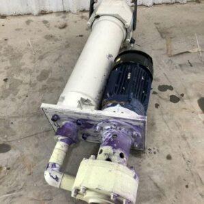 Renner 2000091604 4.8kW PP Sealless Immersible Chemical Pump 3PH 310lpm
1 × $500.00
Renner 2000091604 4.8kW PP Sealless Immersible Chemical Pump 3PH 310lpm
1 × $500.00 -
×
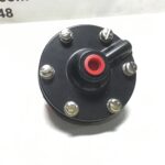
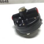
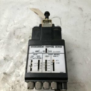 24Y1854B3 175A Overcurrent Tripping Device 60Hz
1 × $50.00
24Y1854B3 175A Overcurrent Tripping Device 60Hz
1 × $50.00
Subtotal: $550.00


Reviews
There are no reviews yet.